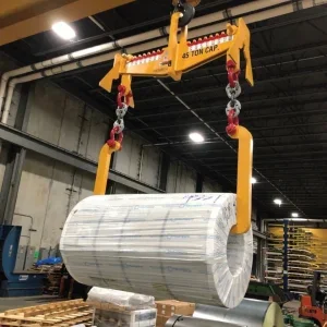
Steel industry C-hooks, coil grabs and tongs are among the least expensive processing and material handling components. Yet their working value far exceeds an initial investment. When a shipping department cannot move coils off the dock due to a broken coil, or a furnace must be shutdown because of a cracked bushing in the ingot tong linkage, the equipment’s true cost is revealed. Thorough maintenance and inspection can improve productivity by reducing equipment failures and downtime while extending useful life.
Equipment owners’ manuals contain inspection and maintenance information. ASME/ANSI Standard B30.20 (ASME – American Society of Mechanical Engineers; ANSI – American National Standards Institute) Below the hook lifting devices also offers excellent equipment inspection and maintenance guidelines. Most owners and operators, however, are searching for additional instructions for recognition of frequently occurring problems, acceptable tolerances and appropriate maintenance procedures.
Bushman Equipment has identified effective inspection and maintenance practices for most common mill duty material handling equipment including C-hooks, coil grabs, tongs and load beams. The following information examines inspection result evaluation and recommendations, to establish maintenance procedures for maximum equipment operating life. It serves to supplement ANSI standards and owners’ manuals produced by manufacturers.
Inspection frequency
ANSI B30.20 provides essential lifter inspection guidance in two categories – Frequent and Periodic Inspections.
Frequent Inspections are usually performed visually by the operator or other designate, and are based on lifter duty cycle. Frequency may range from daily to monthly for most lifters, with no records required. Common conditions that are targeted include:
• lifter or part deformation
• cracks
• excessive wear
• loose or missing guards, fasteners, covers, stops, or nameplates
• operating and automatic hold/release mech- anisms affecting safe operation.
Although not required by ANSI, any discrepancies, adjustments or maintenance actions should be recorded in the lifter maintenance log for future analysis.
Periodic Inspections are recorded, and are very useful in providing trend data over long term lifter life while identifying potential problems prior to failure. Inspection frequency usually ranges from quarterly to yearly. Inspectors search for deficiencies and identify hazards, including: loose bolts or fasteners; cracked or worn gears, pulleys, sheaves, sprockets, bearings, chains, and belts; excessive wear of friction pads, linkages and other mechanical parts; excessive wear at hoist hooking points and load support clevises or pins.
Dye-penetrant checks for weld and other critical area cracks should also be conducted. Paint, oil and other debris should be removed from critical areas before performing these checks.
Specific scheduling information for Frequent and Periodic Inspections is detailed in Table 1 of ASME/ANSI B30.20, and most owner manuals.
Bail wear
Wear is normal and depends on several conditions including:
• lifter and hook material composition
• lifter duty cycle
• surface profile type between hook and bail determined by seating surface
• operator load handling habits.
Certain bail material may result in substantially more crane hook wear than on the lifter.
Examine bail assemblies for weld, base material, and structural cracks, including assembly to lifter metal connections. For single-piece (burned plate) bails, search for seating surface that has ‘mushroomed’ as this can promote hook wear. Inspect for bail bending or deformation caused by side load. A bent bail could indicate the metal has yielded and therefore should be replaced. Bail pins should also be checked for cracks since they have often been heat-treated to make them stronger but this also makes them more susceptible to cracks. Consult the owners’ manual or the manufacturer for acceptable bail wear material loss limits.
Heat-treated bail pins should be dye-penetrant checked in Periodic Inspections. Keeper bars and other retaining devices designed to prevent lifter bail pin release should also be examined for proper installation and operation.
C-hooks
Conduct a frequent, visual inspection of the entire C-hook, focusing on bail wear, bent bail, bent lower arm, and missing manufacturer’s nameplate and safety labels. Examine the C-hook crotch for cracking, while verifying that coils’ inside edges are not gouging out C-hook metal. Cracking paint at the crotch, not evident on other parts, may also signal problems. Base metal may yield more than the hardened paint layer on the surface, causing paint to crack. Any indication of coil and C-hook crotch contact could warrant a change of coil handling procedures. Continued contact of metal on metal at the crotch can create a site for crack initiation.
Welds holding counterweights to the C-hook should also be inspected. Failure of these welds could be hazardous to operators and equipment. Steel coil saddles and any coil protection pads on the C-hook nose or back vertical riser, revolving belts and other assemblies should be inspected. Users should determine a quantifiable set point (allowable degradation of the protective surfaces) for maintenance replacement parameters.
For Periodic Inspections, previously described procedures are performed and recorded for trending data, including dye-penetrant checks at the C-hook lower and upper crotch, where there should be no base metal cracks. The same checks should be made at all base assembly (and bail pin, if applicable) welds. There should be no cracks in the welds or in the pin’s base metal.
Examine the lower arm, determining if it is no longer parallel with the C-hook, or bent downward, and resulting from excessive loading. Use a straight edge to check if the lower is parallel to the rest of the assembly, allowing a 1° to 2° variance. For detection of excessive loading, measure the inside dimension between the C-hook’s upper part and lower arm. More than half an inch (12.5mm) variance is unacceptable.
C-hook maintenance normally requires only replacement of wear pads or other coil protection options. No C-hook or other component welding should be conducted without first consulting the manufacturer since many C-hooks and other parts are made from special alloys, requiring special procedures. Unit integrity could also be compromised. ANSI/AWS D14.1-97 Specifications for welding of industrial and mill Cranes and other material handling equipment gives direction on field welding repair and modifications.
Motorised coil lifters
Frequent visual inspections of the entire coil lifter should emphasise several potential problem areas: bail wear, smooth slider operation, smooth grab rotation (if applicable), all attached guards and stops, and manufacturer nameplate and safety labels. Secondly, examine all lifter related safety features – those interlock devices designed to prevent loss of load control.
Many coil lifters recognise coil engagement and disable the grab’s ability to open sliders. These devices should be checked without a load to verify proper operation. Compressing pad switches followed by attempts to open the grab is one testing method. Flappers or proximity sensors for prevention of coil damage must also be examined.
Visual slider inspection should reflect several specific actions. Examine surfaces for acceptable greasing and presence of excessive gouges; check slider ‘knee’ (90° turn position where slider becomes the vertical leg) for cracks. Review coil horizontal pad for cracks at the leg crotch. Inspect attachment point welds between lifter and crane. Verify that attachment of bail pin and retaining devices is in proper working order. And check the bail pin or bail as described in the section on bail wear. Any weld cracks deemed hazardous to structural integrity warrant tagging a lifter ‘out of service’ until repairs are complete.
All power should be disconnected at source and verified that it is de-energised with a multi-meter prior to electrical inspection in accordance with ANSI Z244.1 Personnel protection lockout/tagout of energy sources. Following power disconnect verification, the plug and cabling between crane and lifter should be examined. No plug and receptacle housing cracks or signs of loose wiring should be visible. Check cord grips for installation at the plug/receptacle and frame’s junction box. Inspect the control pendant (if applicable), looking for fraying cable, cracked/broken enclosure, and presence of proper cord grips.
Visual inspection inside the electrical control enclosure should reveal no cracked or burned wire insulation, foreign material or loose connections. Further examine wiring to sensors and motors outside the enclosure, being mindful of frayed wires, sliced insulation, stretched/taught wires, discoloured insulation or broken connectors. When re-energised, all lifter pendant operations should be tested for proper function.
Mechanical drive and any rotating components should be inspected, checking for:
• wear and alignment
• the integrity of bearings, chains, belts, couplings, clutches and other drive line components.
Problem indicators include:
• misalignment or wear
• presence of metal shavings or foreign material near drive components
• improper chain and belt adjustment
• absence of greasing and lubrication
• drive system noises or irregularities in operation.
Additional Periodic Inspection procedures important for trending purposes are dye-penetrant checks for base metal cracks at the horizontal pad crotch that supports the coil, and dye-penetrant checks for cracks of all bail assembly and slider structural welds.
Record drive component bull gear alignment to establish significant changes to drive components. Such changes between the bull gear and drive components can determine abnormal wear or potential bearing failure.
Measure the clear height (sliders extended), or distance between the coil’s horizontal pad and lifter frame bottom. Record the clear height with the sliders closed and open. While some variance will occur, sharp clear height increases, or sliders hanging up when fully extended, can indicate excessive surface wear or more serious structural problems.
Examine legs for simultaneous operation. For unit coil grab drive and idler side configurations, measure the difference between initial drive movement and idler activation, using dial indicators to determine movement difference. Sharp increases over time can reflect bearing, chain, or belt failure.
Tong grabs
During frequent visual inspections, examine the entire tong grab for bail wear and smooth linkage operation. Check the safety latch. Ensure that the manufacturer’s nameplate and all guards, stops and safety labels are attached. Inspect the bail, determining possible material loss at the tong/hook interface. (See section on bail wear.) Inspect tong linkage pins. If more than 2% to 5% wear is evident, consult the manufacturer for replacement.
Check the automatic latch for peening or wear at the piston/catch interface. Examine linkage pins for deformations resulting from possible overloading. Check collars, roller and cotter pins for proper operation or absence. Check bushings for cracks or wear. Inspect linkage for play, a precursor to worn retaining devices or worn bushings/bearings.
Examine tong legs for straightness and centre location when closed, being mindful of base metal deformation resulting from excessive loading. Examine pads for proper swivel or rotation. Inspect pads for wear and possible replacement. Important note: interface points must be maintained to insure integrity of the original design.
Lifting Beams
Lifting Beams come in many different configurations, but the inspection of them is very similar. The Frequent Inspection starts with a complete overall review of the beam which looks for:
• obvious material deformation
• bent hooks
• missing retaining pins, keeper bars, safety signs or manufacturer’s labels.
For beams with adjustable lifting points or bails, inspect the mechanism that holds the assembly in position. Check that it has not worn to the extent that the assembly could slip out of position during a pick. Pins, clips, shackles, links, hooks and slings should also all be in proper condition.
If there are pins or other retaining devices to prevent the load from being released, check they are sized properly (in case they have been substituted from the original design).
Next step is a visual inspection of the beam for obvious weld cracks or other signs of deformation. Cracks in structural members would warrant the beam being tagged ‘out of service’ until repairs can be made. Cracks in spacers or other non-load bearing members need to be evaluated to determine if they would be detrimental to beam operation. The bail or bail pin between the crane and the beam should be inspected for obvious wear and excessive indications. (See section on bail wear.) If the beam is made of channel, I-section or other structural members, checking the straightness of the beam may indicate if the beam has been subjected to excessive forces or loads. A simple piece of string pulled taught along the edge of the structural member will determine the difference in the camber and sweep of the lifter. Anything out of alignment should be investigated.
During Periodic Inspections the same inspections as above are performed and recorded for trending data. In addition, dye-penetrant checks are performed at the critical loading areas on all hooks or other members that connect the load to the beam, and at all structural welds in the bail assembly and the beam.
Maintenance of a load beam is usually limited to replacement of protective pads, liners or hardware that attaches the load to the beam. On beams with adjustable bails or hooks, proper greasing of the contact points is advisable.
If the lifting beam is motorised, many of the items covered in the motorised coil lifter section will apply.
Conclusion
Mill duty equipment is usually designed for severe duty cycles and minimal maintenance. Inspection criteria and maintenance procedures in this article are based on experience of maximising lifting equipment longevity. They are not intended to supercede original manufacturer recommendations or ASME/ANSI B30.20.
Lifting equipment inspection and preventative maintenance are prudent procedures designed to improve overall manufacturing line productivity, ensure a long useful life and deliver a better return on your material handling investment.


