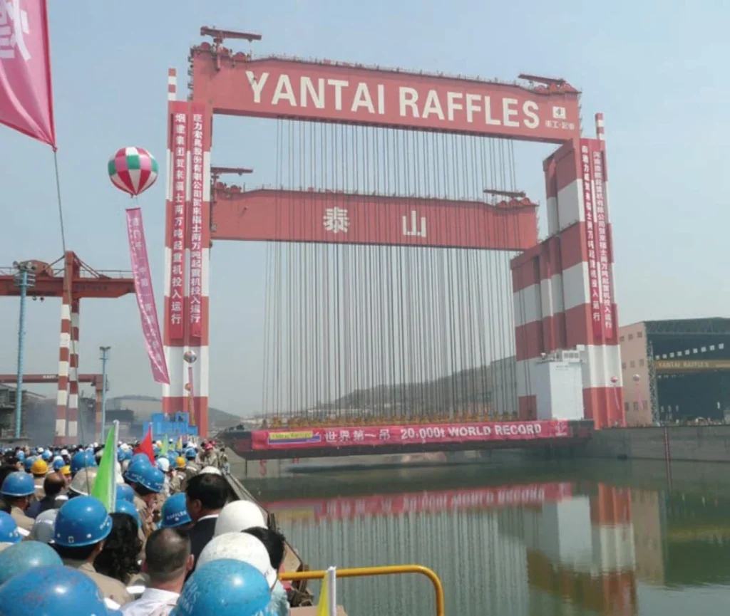
The highest-capacity crane in the world is a gantry crane. It is the Taisun crane at the Yantai Raffles shipyard in Shandong province in China. It has lifted and has a safe working load of 20,133 tons. Such ultrahigh- capacity cranes are commonly called Goliath cranes and have a traditional and current use in shipbuilding.
Next down in size can be gantries used as process cranes, the ones that feed incoming materials – logs, scrap steel and the like – from a stockyard into a factory or power plant. Frequently they are automated, since the work is largely repetitious and predictable; frequently also the crane works both outdoors and indoors: it runs on rails that go from the open-air yard into the covered building. Nomenclature becomes tricky here and remains so. Such cranes are also called portal cranes – the portal being the large empty space spanned by the gantry beam – but they are all gantry designs.
Intermodal use, as in transferring containers from rail to trucks, is another typical application for the larger sizes of gantry crane. Ports have their own types: RTGs, rubber-tyred gantry cranes, and RMTGs, rail-mounted gantry cranes, are standard equipment and even the shipto- shore cranes that load and unload giant container ships are commonly called gantries, though they probably should not be since their design and load-bearing paths are very different. We shall in this article leave such dockyard evolutions of the theme aside.
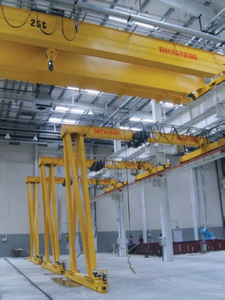
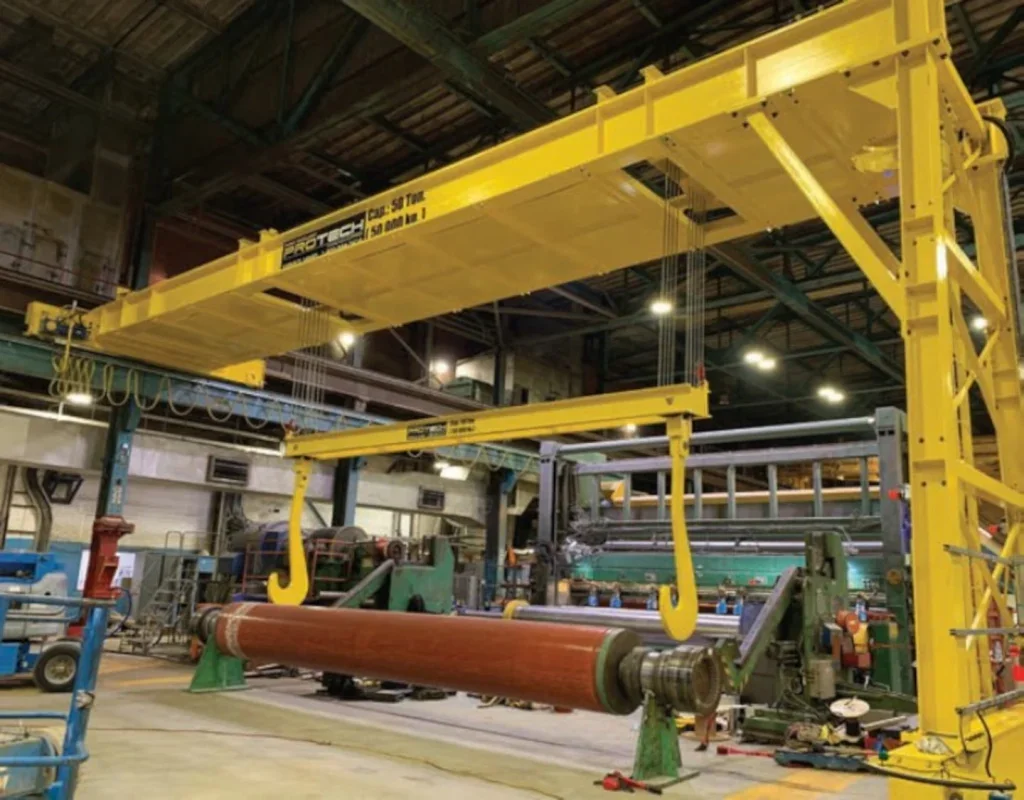
Still further down the scale midsize gantry cranes are found in fabrication plants and factories; and ultra-small manpowered ones, pushed into position and with manual chain hoists running along the beam are ubiquitous in automobile repair shops and the like, where they are ideal for lifting engines from vehicles and indeed for any load that is a bit too heavy for one man to handle.
So, we are talking multitudes here – multiple sizes, multiple applications, multiple environments, but all sharing a common basic design.
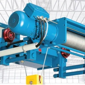
First, some definitions: what exactly is a gantry crane? It is, speaking strictly, clear enough: it is a beam that is supported on legs at each end. A hoist can move along the beam; and the legs can move along the ground. Coverage is therefore rectangular; and the load can be moved with simplicity in all three dimensions.
But nothing is ever quite as clear as it seems. Some users, some manufacturers even, use the terms ‘gantry crane, ‘bridge crane’, ‘girder crane’ and ‘overhead crane’ interchangeably. New Jersey-based manufacturers and crane servicers Sissco explain the difference: Bridge or girder or overhead cranes are supported at height, on rails that rest on tall columns or on the walls of the building. Gantry cranes are supported on their own legs, and the legs run along the ground on rails or on rubber tyres. Gantries are therefore self-supporting; the others are part of the structure of the building that houses them.
As Sissco point out, of the two designs gantry cranes are the more flexible. Because they support themselves on the ground they are independent of the building in which they are situated; so can be put into any building, irrespective of the strength, if any, of that building’s walls and without needing pillars or columns to be constructed to carry overhead rails. For the same reason they do not have to be custom-designed. Both of these factors make them economical to install.
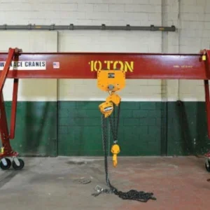
The footprint over which they can operate is large and conveniently rectangular; a wall-mounted jib crane, also commonly found inside manufacturing plants, in contrast has a semicircular operating area, which in real life is far from convenient: how many of us live or work in semi-circular rooms? Also of course gantry cranes have much greater lifting capacity than a wall-mounted jib crane, which generally are designed for lighter loads. However, the overhead or bridge crane can come in double- or even triple-girder forms. Almost all gantry cranes (apart from Goliaths) are single-girder. For indoor applications carrying the very heaviest of loads, therefore, overhead bridge cranes will generally have the advantage.
The main consideration between these two types of crane, overhead versus gantry, therefore comes down to capacity and strength on one side, versus flexibility, and simplicity and economy of installation, on the other. Cranemakers Pelloby, a division of Chesterfield Crane Company based in Derbyshire, are currently, and conveniently for this article, illustrating the ‘flexibility’ part of that statement. They are in the process of transporting an existing 12.5 t SWL gantry crane some 60 miles to a new site in South Wales (See box.)
For completeness we should mention also the semi-gantry crane, which has a slight crisis of identity being both a gantry crane and an overhead bridge crane. One end of it has legs that run on tracks or tyres along the ground so qualifying as a gantry; the other end runs on an elevated runway fixed to the wall of the building, so qualifying the machine as an overhead or bridge crane. Semi-gantries are found in roughly equal numbers inside fabrication plants and outside.
The advantages of the hybrid are clear and apply indoors or out: it saves on space, the footprint is large, rectangular, and obstructed, if at all, only by a single rail on the ground. It is economical, since a wall of an existing building provides half the structure that gives height; and geography is on its side as well since storage yards, for components going in or for finished products coming out of a building, are most conveniently sited alongside that building, so using one wall of that building to support the hoist makes sense: it is close by and no space is wasted since the loads can be stored right up against the wall.
As lifting solutions go the gantry design does seem an obvious one – a beam supported on legs at either end – and it has been used since earliest times.
A travelling gantry though does though have a weakness, or at least a consideration that designers must address. For smooth movement along the ground the leg structures and the wheels at either end must be kept aligned and parallel to each other. But the beam is large and long: if the legs were to be fixed rigidly to it, then any deflection, twist or expansion of the beam – from load, or from wind, or from thermal expansion in hot weather, – would transmit itself, magnified, to the legs and wheels; rubber-tyred wheels would then not travel in a straight line, and rail-mounted wheels might jam.
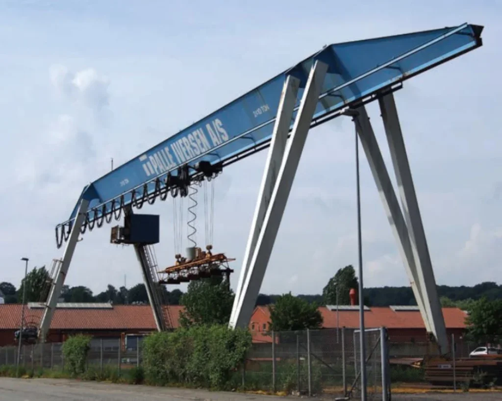
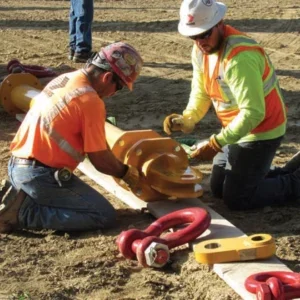
The solution is some kind of flexible joint where the top of the leg meets the beam. Only one set of legs needs such a join. (If both ends were flexible, the whole thing would collapse sideways; it would be a mechanism, not a structure). That is the reason that large gantry cranes, where wind load and thermal expansion of the beam become significant, are frequently asymmetrical. The legs at one end are larger, more rigid, of a quite different design that legs at the other.
A related problem afflicts small – even the smallest- of portable gantries such as those used in repair shops. These gantries are generally manoeuvred along the ground by hand. They run on four wheels, usually small casters. If the hoist lifting the vehicle engine is not positioned in the middle of the beam, the load is not centralised; then if the gantry is unduly rigid, the wheels will carry uneven loads. Worse: if the floor is anything but completely flat – and concrete floors in repair shops are frequently chipped and uneven – then one of the wheels may lose contact with the ground completely. As well as making it harder to push, the gantry may tip or tilt; with obvious risk to safety.
So, again, over-rigidity is to be avoided. It may be simply that the beam can flex a little, enough to generally compensate in most cases for mild unevenness of the floor; it may be more sophisticated than that. Thus, Pennsylvania makers Wallace, who have been making small gantry cranes since 1954 and who claim to have more gantry cranes in use than any other manufacturer, have their patented pin-joint design. A pin-jointed four-bar link joins the legs to the beam; the beam in effect is hanging from the apex of an A-frame. The arrangement allows it to swing slightly and makes it self-centering upon the legs. The legs at their lower end are also pin jointed, to the frame holding the casters. The arrangement serves several purposes. The self-centering beam reduces torsional, or off-angle loads in the legs, so stresses there are reduced. The casters and frame flex, so that the four wheels are always in contact with the floor. Not only that, but the design ensures that the load is distributed among all the casters. Even if the load is entirely at one end of the beam the load is evenly distributed between the four wheels.
Wallace Cranes do have a word of caution about the surfaces that portable gantries are run on. Because the load of the crane is transmitted to the floor through the casters – essentially as a point or line loads rather than being distributed – the flooring beneath a crane must be able to bear that load. Wallace suggests that it should be of 3,000 psi (7,000 N/m2) concrete at least 18” (45cm) deep with one or more courses of rebar. The standard Wallace casters, in either phenolic or steel core with polyurethane tread, are fully capable of smoothly running the crane across the floor at full load.
An alternative option is to have the crane track mounted. For these cranes, typically with an electric motor drive, the casters are replaced with V-groove steel, running on a track made of angle iron mounted on a plate. Wallace builds this track in-house with three different capacities, 1-5 tons, 8-10 tons, and 15 tons. The track sections are available in standard 5 and 10-ft lengths, with male and female sections for smooth running. Wallace also makes ta removable transition section for high-traffic areas.
Many small portable gantries can be disassembled for storage, and Wallace cranes are no exception. The pinned joints make assembly and disassembly easier. Parts rotate and the design allows for some misalignment, which means that pins go in easily – the only tool needed is a small hammer – which speeds up initial and subsequent reassembly and reduces the likelihood of assembly-induced prestresses which could reduce crane life and reliability.
Wallace gantries are available in capacities from ½ ton to 15 tons, in fixed or adjustable heights and spans. Beam length and height can also be customised.
So if it is a gantry that you need, there are hundreds of different sizes and there will be one in your size available. But as for shape, one shape fits all. But still, it is a good shape. It will work for you.
KULI CRANES
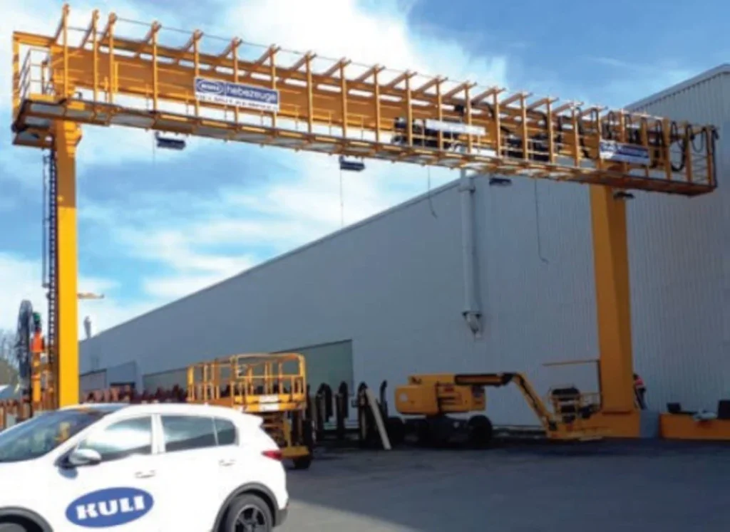
Kuli Hebezeug Cranes have been making cranes in Remscheid in North Rhine-Westphalia for a hundred years. They recently delivered a gantry crane to a customer also in Remscheid, very close to their own facilities. The new crane replaces an existing one. The customer’s needs for the new equipment were higher speeds, greater capacity, and better hook approaches, together with more sensitive operation and smoother running.
The new crane has a lifting height of 14m and a runway length of 90 m. It has two 3,2t hoists, mechanically coupled, to give a maximum capacity of 5t. The distance between the hooks is a fixed 4m. The span is 20m with a cantilever at one end which has a usable length of 0,5m. All movements are frequency inverter driven with stepless speed adjustment to give lifting speeds of 0-10m/min and crosstravel speeds of 3.6 – 36 m/min. Longitudinal travel is from 4 – 60 m/ min. A special lifting traverse is fitted, 6m wide with 6 cow-horn hooks (please see picture). Safety fitments include anemometer, slack rope detection, and a load summing device to keep to the maximum 5t capacity. There is a crane activity signal inside the building to show that the outside gantry crane is in motion. Operation is by radio remote control. The design is to DIN 15018 for lifting class H3B4.
The total crane weight was around 20t. Two 50t and one 35t truckmounted cranes were needed for the on-site erection.