Any failure in a crane’s welded structure can lead to loss of life and/or damage to equipment. Determining a crane’s structural integrity can be an expensive and time-consuming process, particularly when the surface coating has to be removed and sometimes even disassembly is required. A UK-based company, Technical Software Consultants Ltd (TSC), manufactures equipment used to detect and measure surface breaking fatigue cracks in metal structures. The technique is non-destructive and does not require removal of surface coatings up to 6mm thick. TSC’s equipment has recently begun to be used on cranes.
Apave Group, a French government appointed inspection body, carries out third party inspection work in many different areas including dockside lifting equipment. TSC’s alternating current field measurement (ACFM) technique was used to inspect the critical welds of a container crane in as little as six hours.
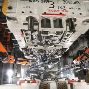
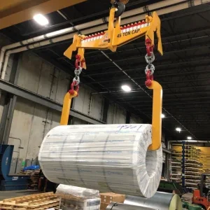
Many types of lifting equipment found on docksides around the world, claw cranes, grab cranes and container cranes for example, have been adapted to handle accelerated work cycles and larger ships.
In addition to the normal wear of moving parts, the metal structure of the crane is subject to stresses and environmental conditions that make it prone to degradation through fatigue and corrosion. Without a suitable inspection technique, cranes can be removed from service simply because of their age, even though they may still have useful life left. Or if the surface coating has to be removed for magnetic particle inspection and then reapplied, the crane can be out of service for weeks.
Detection technique
The ACFM technique was developed from the AC potential drop (ACPD) technique which has been used for crack sizing and crack growth monitoring. ACPD has been used under water even though electrical contact has to be maintained between the probe and the component being inspected. The ACFM technique is said to be simpler in operation because it depends on the measurement of near-surface magnetic fields rather than the surface electric fields, thus requiring no electrical contact. Theoretical work carried out at the Wolfson NDE Centre in the Mechanical Engineering Department of University College London determined the relationship linking these two fields. Thus existing models of electric fields around cracks can be used to size cracks using magnetic field measurements. This non-contacting sizing capability relies on the use of unidirectional input current in the region under inspection, similar to that required for the ACPD technique. For the ACFM technique, the input current is induced into the specimen thus making the system fully non-contacting. The instrument used is the U9.b Crack Microgauge marketed by TCS.
In single probe ACFM operation the Crack Microgauge passes two signals to the ACFM crack detection and sizing software (QFM). The first is the magnetic field strength measured in the direction parallel to the crack edge (Bx) and the second is the magnetic field strength measured in a plane perpendicular to the surface of the metal (Bz). The software (QFM) then displays these signals in three forms; the Bx and Bz traces separately against a timebase, a dual digital meter display, and a polar plot display in which one component is plotted against the other. This latter form is known as a butterfly plot because of the characteristic trace produced by a defect.
Advantages
Conventional inspection techniques, such as penetrant examination and magnetic particle examination, generally require careful preparation of the surface prior to inspection. The ACFM technique enables detection of defects through non-conductive coatings that are several millimetres thick, so framework welds can be examined directly on painted or dirty surfaces.
As the areas to be inspected are often inaccessible, aerial platforms and scaffolding are often needed. In contrast, abseilers can move remote controlled ACFM probes over the surface to be inspected. This rope-based approach allows quick and easy access to the inspection areas at reduced cost.
TSC claims that Apave’s experience shows that ACFM testing is at least three times quicker than conventional methods. And as all operations are recorded, the data obtained can be stored and analysed.
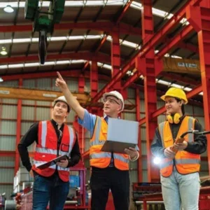
Inspecting container cranes
Dockside container handling cranes can be made of more than 1,000t of steel. Lifting heights can be 45m with loads of up to 70t and the overall height of the structure can be 70m above the dockside. The first part of an inspection is to define the critical areas of the structure that are susceptible to cracking from fatigue stress and to visually inspect the structure. When loads are lifted the jib is subjected to combined bending, shear and tensile-compression strain. No cracking is permitted on these components. Crossbraces and stiffeners are less critical in terms of small defects, but inspection is still required.
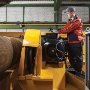
Much of the stress is concentrated in the steel front and rear ties that support the boom. In general, the rear tie is a tubular section and the front tie is an ‘H’ section member. The front tie is attached at each end by a shaft through a welded block. It must fold back when the crane is at rest so it is hinged on shackles. The entire length of the weld seams are inspected using ACFM with an edge-effect correcting probe and the shafts are inspected ultrasonically.
A one-metre-diameter, helically welded steel tube forms the rear tie which is held at each end by a fabricated reinforcing part. The butt welds on the tube and on the upper and lower attachment points are inspected using ACFM. The probe is moved over the welds following precise scanning directions. Particular attention is given to the corners of the reinforcing gussets where cracking occurs.
The rest of the structure is inspected visually and any suspicious areas are subjected to non-destructive examination. If defects are identified in any area then all other equipment is also inspected.