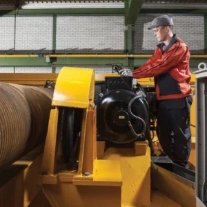
Figs 1 and 2 show two views of a load handling clamp for which the load handling control in the invention can be used. This is a hydraulic, pivot-arm clamp with a base (15) designed for mounting on a lift-truck carriage, capable of moving up and down its mast. (11 in Fig 3). The mast can also be tilted by hydraulic cylinders (13 in Fig 3).
In this particular example, the clamps are used for paper rolls, which, if subject to excessive clamping force, will become too distorted for use on high-speed presses or other machinery for which they are intended. Conversely, inadequate clamping force can cause the roll to slip down. The invention is designed to prevent these problems.
Although the mechanism shown in Figs 1 and 2 is the preferred embodiment, clamps operated by the invention can be used in many other applications, says the Patent, including with sliding rather than pivoted arms, and/or able to handle rectilinear rather than round loads.
How it works
The clamp is closed by extension of the hydraulic cylinders (32 – Fig 3), with the maximum pressure regulated by a valve assembly (75) with a pilot control comprising a variably controlled relief valve assembly (74). This assembly preferably comprises a single relief valve with a relief setting infinitely proportional to a variable signal received from an electrical controller (70) via signal line 76.
Alternatively the maximum pressure can be regulated by a valve or valves with different settings automatically selected by the controller, or by automatically variable pressure-reducing valves in line 54 with output pressure settings regulated by the controller.
As the clamp arms are closed on the load, the controller operates in accordance with a set ‘decision making’ sequence and according to initialisation values previously entered into the controller by the operator using keyboard switches such as 118.
During the initial clamp closure the controller sets the variable relief of the valve assembly 74 at a relatively high level previously selected in initialisation. This enables high-speed closure of the clamp prior to actually gripping. In response to the contact with the load-engaging surfaces the pressure in line 54 is sensed by 78 to increase above a minimum pilot pressure previously set.
At the same time, the flow in this line reduces, causing a corresponding decrease in the positive differential between the pressure reading at sensor 78, and the reading at sensor 66. This comes down to a limit value preset by the operator. In response to this change, reflecting a predetermined resistance by the load to further closure of the clamp arms, the controller immediately reduces the relief setting of valve assembly 74 to a preset low threshold level selected by the operator from three alternatives.
This decreases the pressure, between the pilot-operated check valves 50 and the operating cylinders, to the reduced relief setting, ensuring that the high-speed closing pressure is not maintained. The reduced pressure is the threshold gripping pressure from which subsequent increases in gripping pressure will be automatically regulated as below.
It is also possible to use other predetermined relationships between the load and load-engaging surfaces to trigger pressure reduction, such as proximity. Once the threshold gripping pressure has been established the operator moves valve 36 to its unactuated position and begins to lift the load via valves 80 (hoist control) or 82 (tilt control). A pressure sensor (92) reacts to a subsequent increase in pressure in line 88 and signals to the controller that lifting has begun. The controller actuates solenoid valve 94 allowing the flow in line 43 to go through line 54, further closing the clamp arms.
The controller senses the weight of the load by a signal from sensor 92. Consequently it increases the relief setting of valve assembly 74 in a predetermined relation to the load’s weight. Accumulator 87 minimises dynamic effects of the load-weight measurement action, maximising the accuracy of the measurement. Dynamic effects can be further minimised by installing a limiter in line 54 for lifting speed.
Once the maximum gripping pressure has been reached the controller deactivates solenoid valve 94, so that automatic gripping pressure regulation ceases. The controller sets valve 74 to prevent further increase in gripping pressure despite any operator action. The system then begins continuous monitoring of the gripping pressure relative to the sensed load weight with any necessary adjustments as below.
The operator’s manual actuation of the tilt control valve 82 also initiates the load-weighing and pressure-regulating operation as above.
As alternatives to fluid pressure sensors 66, 78 and 92, appropriate flow meters and/or electromechanical force sensors could be used.
Compensation factors
The accuracy of load-weight measurement is enhanced by compensating for variations in the extension of the lift-truck mast, varying the reading of sensor 92. There may be various causes for this, and to account for these variable, as well as variable in the load-handling clamps that may interchanged on the mast mountings, the controller is initialised to calibrate in the variables using operation without a load and with a known load weight. The controller stores the measured pressure values for future reference. Other operator entries using keyboard switches include one or more desired clamp-force-to-load-weight ratios, and a ‘clamp factor’ representing the total effective pressure area of the combined clamping cylinders, multiplied by the efficiency percentage of the clamp cylinders.
The latter corresponds to the ratio of the clamp force generated by the load-engaging surfaces to the product of the effective pressure area of the combined clamping cylinders and the applied fluid pressure.
All the initial parameters need be entered only for new installations or for changes of the load-handling clamps or masts. Other controller entries are only required for new parameters, with no entries for unchanged operational parameters.
In the load-clamping sequence the controller regulates the load-weight measurement and gripping pressure by automatically accounting for the range of mast extension, different desired clamp-force-to-load-weight ratios, and other variables.
According to sensors of the mast position, the controller sets the future load-weight calculation with parameters appropriate either for the freelift range of mast extension or the mainlift range of extension.
After actuation of solenoid 94 in response to the operator actuating the hoist or tilt valves, the controller reads the lifting pressure sensed by 92, and then calculates the load-weight using the appropriate freelift or mainlift calculation according to formulae set down in the Patent.
The controller then determines the desired clamp force according to the clamp-force-to-load-weight ratio previously selected by the operator. It then calculates the maximum fluid gripping pressure according to the previously entered clamp factor, and adjusts the maximum pressure relief setting of valve 74 to the desired maximum gripping pressure. The process is repeated continuously until the controller determines that the actual gripping pressure sensed at 66 equals or exceeds the desired gripping pressure. The controller then deactivates solenoid 94 and sets valve 74 to prevent manually activated pressure increases, as before.
The system continuously monitors that the load is being supported by the clamp according to the hoist pressure according to the pre-set values, making any necessary readjustments made necessary by such variables at hydraulic fluid leakage or the load initially not being fully supported.
The monitoring and any necessary correction operations continue until the system senses that the operator has set the load down. Once the operator has opened the clamp, as sensed by a pressure rise at 98, the load clamping sequence returns to its origin, with a reset of valve 74 to high-speed closure.
Other options
Other devices are optional to prevent damage to the load. For example, to prevent the setting down of a fragile load in a tilted attitude, possibly causing damage to the edge of the load, a gravity-referenced tilt sensor is mounted on the base frame of the clamp. This determines whether or not the load is tilted, causing the controller to automatically adjust the load to a level attitude via the tilt control valve 82. This is irrespective of the mast tilt, or whether the truck itself is on a level surface. However, due to the gravity-referenced sensor 124 being susceptible to disturbance, the controller actuates the tilt control only in response to a decrease in load-weight in response to lowering of the load to set down. During lowering dynamic disturbances are minimised due to stoppage of the lift truck.
Another possible means of load damage whilst setting down is the possibility of the operator continuing to lower the mast before the clamps have been opened. The load rather than the mast will then support the clamp so that, when the clamps are eventually opened, the clamp surfaces will slide down the surfaces of the load, causing external damage to fragile loads such as paper rolls. To prevent this a solenoid valve (47) can be provided downstream of valve 45, with automatic operation by the controller.
This prevents further lowering of the mast until the clamp arms have been opened. During lowering of the mast and optional restrictor 35 can be used to limit lowering speed to maintain the accuracy of pressure sensing at 92. The lowering prevention system is also applicable to other types of loads and load-engaging structures, such as forks, to prevent free-fall of the load-engaging structure when disengaged from the load.
With the use of the electrical controller, the authors claim improvements over previous types of adaptive load-clamping systems proposed previously.
- This article is an edited version of US patent 7,018,159. The inventors are Dean Clark Jordan of Gresham, Oregon and Richard D Seaberg of Brush Prairie, Washington state. The assignee is the Cascade Corporation of Portland, Oregon, and international manufacturer of materials handling equipment specialising in forks and attachments for forklift trucks.
- This article is an edited version of the patent and may omit legally or technically important text. To see the full patent go to www.hoistmagazine.com/patents.