The often solid structure of cranes makes them subject to abuse, error and neglect. Usually this does not create immediate problems or failures. Heavy duty cranes, in particular, normally have a relatively higher rated capacity and even a 100% overload would probably not be of any immediate danger. However, the degradation of wire rope will dramatically increase as a result of the overload. Wire ropes are already exposed to considerable wear in normal use. The wire rope is the most vulnerable part of the hoist.
Several studies of overhead travelling cranes show that the large majority of dropped loads are caused by one of two types of wire rope failure: rope damage and overstressing. Preventing these two causes would reduce the frequency of load drops by about 90%.
Often the operator is to blame – trying to lift loads that are too heavy, or operating with the rope out of the sheaves. Insufficient maintenance is also a frequent cause. Whatever the reason, if the load drops it is usually because the wire rope has failed.
What causes wire rope to break
Wire rope will break if it is structurally damaged or if it is overloaded. Damage will be caused if the rope is misreeved, with the rope leaving its grooves on the drum and/or sheaves. This is usually caused by off-centre lifts, hoisting while the load is swinging, or by slack in the rope system, which can cause the rope to leave a groove and be cut or ‘kinked’ under load, or wrap around the drum shaft or sheave axle and cause rope breakage or shaft failure.
More common is overloading, of which there are several types:
• Over capacity lifts: sometimes over capacity lifts are unintentional, as when the weight of the load is unknown or when the load is attached to something. Unfortunately many overloads are intentional and condoned or even mandated by management. Over capacity lifts are frequently rationalised by the misconception that cranes are so conservatively rated that even a 200% overload is not a real problem. Even if this was true the wire rope is subject to wear and degradation in use, which can substantially decrease its safety factor. Overloads can cause immediate failure but, more often, they have a cumulative effect on wear and fatigue. Wire rope is subject to considerable degradation over time even in normal use. Overloads increase rope wear and eventually become the immediate cause of failure.
• Load hang up: this happens when a load in motion snags on something or when a load is stuck. The kinetic energy of the moving and/or rotating machinery causes overstress on the crane machinery, construction and on the wire rope.
• Two blocking: this is when the hoist upper limit switch is not functioning or another malfunction results in overhoisting to the point where the load block runs into the hoist trolley structure. The inertia of the rotating machinery and the stall torque of the hoist motor cause an immediate wire rope failure. A likely consequence is that the load block and any suspended load will fall.
• Snatching: the load is engaged with an impact caused by the hoist and/or travel motor accelerating to a certain speed before the weight of the load has been taken up. Snatching in combination with an over capacity lift is double trouble.
How to protect wire rope
Wire rope is the most vulnerable part of the overhead travelling crane’s load carrying system. It accounts for a considerable part of the maintenance cost of overhead travelling cranes. How can wire ropes be better protected and thereby increase the safety and cut the maintenance costs of crane operations?
The first priority is to improve operator training. Scheduled and repetitive training for crane operators is a good investment.
The second way to protect wire rope is to use overload guards. Experiences and studies from many years of using overload guards in overhead travelling cranes in Scandinavia and Western Europe confirm the safety and financial benefits of using them. The overload guard makes the responsibilities, decisions and work less of a burden for the crane operator. It can also protect the hoist against two-blocking if the hoisting speed is low.
When selecting an overload guard certain characteristics should be sought. It must be easy to install, sealed to protect it from dust and humidity, and tamper-proof. It should also be easy to adjust the settings. High accuracy (±2% of maximum capacity of the device) and repeatability of the set tripping are also important. Finally, overload guards installed directly on the wire rope must themselves be designed to cause a minimum of wire rope wear.
Mechanical overload guards
There are two basic types of overload guard: mechanical and electronic.
In most types of mechanical overload guard the power-absorbing device consists of spring washers (Belleville washers). The movement of the spring elements affects some kind of device which operates one or more switches.
Mechanical overload guards have the advantages of being resistant to damage, they can work under extreme temperatures, and they are easy to install and adjust.
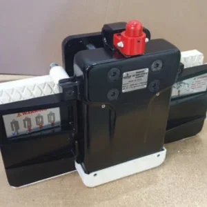
They work in one of two ways. The tension meter type of load guard is made for controlling cranes, lifts, tension control of belt conveyors and for other automatic power-sensing load control. The pull rod movement operates one to five switches through spring-loaded contact points. Normally this instrument is built into the dead end of the wire rope i.e. the stationary part.
The second type of mechanical overload guard is based on rope deflection. The limiter is attached to a stationary part of the wire rope and the rope is deflected through a slight angle between the two wheels and the clamping jaw. When loaded the rope has a tendency to straighten and the pull-rod will start to move out when the tension in the rope exceeds the calibrated force of the load cell. This movement actuates the limit switch.
Usually this type of overload guard is calibrated at the factory but it can easily be reset at the crane site. An advantage of this system is that it does not need to be recalibrated when the wire rope is changed.
It is important that the deflection angle of the wire rope is small, otherwise it will influence the wear of the wire rope. This type of overload guard does not affect the construction of the crane, and so the crane does not need to be re-certified.
Electronic overload guards
Normally an electronic overload guard consists of a power transducer with amplifier and an electronic signal processing unit. The transducer senses either tension, compression, bending, shear and torsion, or combinations of these. The sensor is a strain gauge bridge attached to a load cell made from hardened high tensile steel.
A constant voltage is fed to the foil gauge from the transducer amplifier. A signal is received in return, which is proportional to the force in the load cell. The signal can be processed in the electronic unit for such functions as slack rope switching, overload control, load indication, and recording the number of hoist operations.
An advantage of electronic overload guards is that intelligent technical solutions can be created. One load cell connected to an electronic unit can, as previously mentioned, control against slack rope, give a warning when approaching overload, switch off the hoist at overloading, and provide a voltage or current signal for load indication instruments.
Available today are microprocessor-based electronics which can collect large amounts of important information about the usage of the crane which is useful for condition monitoring and preventive maintenance. We can record full load hours, total service hours, the number of times the overload is triggered, the overload time and the number of hoist movement starts and stops.
All switch value settings and time delays are set on a numerical key pad on a display in the unit, which means that there are no potentiometers to adjust. All records can be called up on the display.
Electronic transducers
There are two types of electronic transducer: load pins and those that work according to the rope deflection principle. The latter type is attached to a stationary part of the wire rope and the wire rope is deflected through a slight angle between the two wheels and the clamping jaw, the same as with the mechanical overload guard.
The difference is that the force applied by the tendency of the rope to straighten under load is transmitted to the load cell instead of straight to a switch. The load cell could also be a bending beam. Normally the output is amplified and converted into a 4-20mA signal before being processed in the electronic unit. This type of power transducer does not affect the construction of the lifting equipment and many load cells of this type can be set at the factory which reduces the amount of installation work on site.
Load pins can be dimensioned to replace, for example, an existing shaft at an equalising pulley or in another part of the crane. The load pin should be installed as near as possible to the force and/or the load to achieve the best possible accuracy.
In many types of load pin the strain gauge foils measure the shear forces in the section between the face of the load (the rope wheels) and the support.
A load pin does not reduce the lifting height of the hoist. More installation and calibration work is needed with a load pin than with a deflection type load cell since it must be calibrated on site.
Whatever system you choose, go to an experienced supplier for maximum reliability. A reliable overload guard will protect your people, your property and avoid losses.


