For many years I have worked with the power generating industry assessing their trainees as lifting specialists. Power stations are full of pipes, pumps, motors, valves, heat exchangers and numerous other awkward shaped items. When the stations are first constructed, access to install such items is generally not a problem but much of it subsequently becomes locked in behind other equipment and relatively inaccessible. The same is true in many other process plants, refineries etc.

As an example of an operation which requires manipulation in the air, let us look at replacing a large valve which could weigh in the order of two or three tonnes. They are usually tall but their shape is such that they won’t stand upright so are normally transported and stored laid down flat on their side. The lifting part of removing the existing valve involves slinging the valve whilst still connected to its pipe work so that when the flanges are unbolted it will be held secure and under control. It then has to be lifted clear, travelled to the landing site and laid flat.
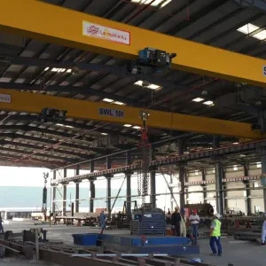
With luck there will be an overhead crane or access for a mobile crane. Otherwise it might be a mobile gantry or some overhead steelwork with limited headroom. Regrettably plant designers don’t always pay sufficient attention to the maintenance man’s future needs.
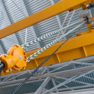
There probably won’t be any attachment points on the valve but a suitable size roundsling in choke hitch behind each flange and another at the valve head should provide a secure three point arrangement. But what about length adjustment? A chain lever hoist is very helpful and is usually best used inverted so that the hoist body climbs the chain. That way it can be more easily reached, and it reduces crowding near the crane hook.
At this point, consider also how the valve is to be manipulated for landing after removal. By selecting slings which can take the whole weight on two or even only one and putting a lever hoist in line with two of them – for example, one of the flange slings plus the one at the valve head – it will give you the facility to lower the valve head and turn it on its axis to land it flat.
Just like the slings, an allowance has to be made for the angle the lever hoist will work at. However if the main lifting machine is a power operated crane, a further allowance should be made for the higher dynamic loading arising from the greater acceleration and deceleration of such a crane compared to a manually operated hoist. This allowance is normally a de-rating of 15%.
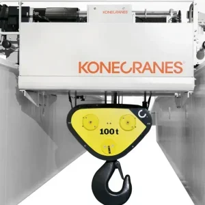
Using a power operated crane has a potential drawback in that the hoist speed and method of control may not provide the incremental movement required to accurately take the tension of a load still connected to its surroundings. A little too much tension risks damaging the pipe work and lifting equipment. Too little risks the load dropping as the last flange bolts are removed and the seal broken. An alternative is to use the crane as a sky hook from which to suspend a hand chain block which will provide the necessary finesse of control for this part of the operation. Once the valve is free, the crane can resume its normal role. As with the lever hoist, an allowance should be made for the extra dynamic loading imposed on the hand chain block when the crane takes over.
There are a couple of points to remember when using lever hoists and hand chain blocks in conjunction with a crane. First, in both the brake relies upon the torque between the load and the hand chain or lever to close it. On lowering it is the load which generates the torque but it is driving back through the friction of the gears. A very light load may not be adequate. As manufactured they should sustain a load down to 5% of the working load limit. However, after a period in service, dirt, corrosion and the like can raise this to nearer 10%. When raising, the brake is forced closed by the effort from the hand chain or lever and slippage is much less likely. Therefore, before hoisting with the crane, it is good practice to make sure that the brake is fully closed by making the last movement a hoisting one, if only by one notch of the ratchet wheel.
The second point is to ensure that the block or hoist is free to align itself in a straight line between its top and bottom hooks. Tempting though it may be, never wrap the load chain around the load as a means of slinging the load. The chain used has different characteristics to that used in chain slings. In particular the tolerances are much finer as it must accurately match the pocketed load wheel and any distortion of a link can cause problems.
Having got the valve firmly held and with the means to control it, it can be released from its fixings. However removing the bolts will usually still leave the gaskets or seals intact and they can take a surprising amount of force to separate. I remember many years ago doing a test on a cast casing held by nothing but paint and it took several tonnes to break the joint. Again it may be tempting to use the lifting equipment but that invites a shock load from the recoil when separation finally occurs. Far better to use other means of separation.
Once free the crane can take over and travel the valve to its landing place. However before setting off remember to check that any hand chains and slack end loops of load chain are safely secured and cannot snag on surrounding objects.
At the landing site, the valve will have to be turned and laid flat on its side for stability. This can be done in the air as a single operation if the slinging arrangement described above is used. Lowering off on the lever hoists will transfer the load onto two slings and turn it sufficient to allow it to be landed flat.
Alternatively the base of the valve can be landed and, by carefully continuing to lower, it can be allowed to topple under control until laid flat. This alternative has its attractions but care is needed. First, once the base has landed and it starts to topple, the crane must move to keep the hoist rope vertical otherwise there is a risk of the load spinning round violently. With an overhead crane, this is easiest if the valve is laid down in the cross travel direction.
Whichever method is used, as the orientation of the load changes, the angles at which the slings are working and the tensions in each will change. The slinger needs to take this into consideration when planning the lift and also monitor closely what is happening as the orientation changes, thinking ahead to avoid getting to the point of no return where a sling slips or is brought across an edge without packing.
Installing the replacement valve is a similar operation but in reverse. However one rather more critical factor is the control in the air and the precision with which the load can be presented to its mating components. In the case of our valve, the flanges must be presented parallel to those on the pipe work and such that the bolt holes align accurately. That requires control to within a millimetre.
Several factors affect this. I have already mentioned the controllability of the crane and the use of a hand chain block to improve control. The flexibility of the lifting structure can also be a problem. Light duty overhead cranes and some mobile cranes can be rather too bouncy for precision positioning. A mobile gantry is very useful in the absence of any other lifting structure but, being portable, they are often light duty and again can be rather bouncy.
Also the majority of mobile gantries are not designed to be moved under load. Therefore they only facilitate travel in one direction, along the line of the beam. This is not insurmountable but does require the lifting operation to be planned in stages, first aligning the valve in one direction, then landing it and repositioning the gantry to facilitate alignment in the other direction.
By carefully thinking it through at the planning stage, selecting the right equipment and monitoring the operation to ensure it is going as planned, it is possible to safely manipulate a load in the air and orientate it with precision into the required position.
About the author
Derrick Bailes is technical consultant (formerly chief executive) for the Lifting Equipment Engineers Association, 3 Osprey Court, Kingfisher Way, Hinchingbrooke Business Park, Huntingdon, PE29 6FN, tel: +44 (0)1480 432 801, fax: +44 (0)1480 436 314, email: info@leea.co.uk.


