This patent provides embodiments that include provision for wire ropes, synthetic webbing straps and coil chains as the tensioned members. These require guide members to maintain the position of the tension members in the housing.
This type of hoist, with high ‘mechanical advantage’, can be used for lifting or repositioning a heavy load, for fine positional adjustment, or for load binding. They may be used in combination with an electric hoist to provide the precision that the electric hoist will probably lack, thus enabling the very precise final adjustment of position of a heavy load. The hoist that is the subject of the patent is designed to make an adjustment of about 0.001 inch (0.025mm) with a input rotation of about one degree.
What it is
The hoist, which includes mechanical use for lifting and lowering, moving horizontally, or securing a load in position, all with the use of flexible tension members including (according to the appropriate embodiment) chains, wire ropes or straps to apply force and tension. These are activated by a load nut with a threaded connection to a load screw that is provided with rotational drive input.
Suitable guides form channel-like spaces alongside the tension members inside the hoist structure through which the flexible tension members travel. These guides maintain the tension members in position even when the tension members are slack, or being fed out of the housing without tension. In most forms of the invention, the guides pass through the load nut.
The screw gear applies a positive hold of the applied tension when the screw gear is not being driven, thus holding the load in position.
How it works
Fig 1 illustrates one embodiment of the invention designed for wire ropes as the tension members (12). The pair of wire ropes can be replaced by four of more ropes (two or more on each side), preferably with a V-groove and pulley for each such wire rope, plus related necessary components for each pair as described below. The use of multiple wire ropes enables the load capacity of the whole device to be increased without requiring heavier, stiffer, ropes. It can also make the device more compact because of the smaller-diameter pulleys required.
The hoist housing (14) provides a frame for the device, generally elongated in shape. There are bearings (16 & 18) at opposite ends of the housing to allow rotation of a screw gear or load screw (20) within the housing. Bearing 18 is a thrust bearing, typically a cylindrical roller thrust bearing. At one end of the load screw is a tool head (22) for engagement by a tool to provide rotational input.
A load screw (24) is connected by a thread to the load nut. This moves longitudinally when the load screw is rotated. The wire ropes (12) are guided within the housing to prevent twisting or kinking when they are slack, such as when the operator is trying to push them out of the housing by back-rotating the load screw. This is accomplished with a pair of V-shaped grooves (25) at opposite ends of the housing interior and extending longitudinally. The inner portions of the cables are confined within the V-shaped grooves by a spring-loaded cable positioner (26) on each side of the housing. These cable positioners are pivotally connected to the load nut and have a spring (a spring coil in dashed lines on the diagram) to bias the elements of 26 towards the sides of the housing and into the V-grooves. This device operates only when the wire ropes are slackened by the operator’s back-rotation of the tool head.
In high tension each wire rope will overcome the spring and assume a taut, straight configuration within the housing.
Each cable has a terminal end (30) connected to a suitable pin or hook (32) on the load nut. Each wire rope leads down to an idler pulley (34) near the payout end (36). The pulleys have a peripheral groove (38) to hold the wire rope as it passes around approximately one quarter of the circumference of the pulley.
Fig 2 is a cross-section through 2-2 in Fig 1 showing both flanges (40) of each idler pulley.
Closely adjacent to each pulley, where it interacts with the wire rope, is a stationary pulley guide wall (42), also part of the housing. This guide wall retains the wire rope within the pulley groove, preventing its escape even if slackened.
Wire ropes are also used in another embodiment of the invention. The ropes are, instead, secured to the load nut at or near the outer ends of the arms of the load nut. Pins again extend transversely from the load screw to support the terminal ends of the tension members. The arms of the load nut are split and spaced apart, extending at the front and back of the flat bar guides. The pins extend between the spaced arm sections.
Straps as tension members
Another version of invention described involves the use of synthetic web straps, which are guided around idler pulleys or rollers, and lying in a groove of the pulleys. In some forms relying on the adjacent walls to maintain the straps on the rollers can eliminate the pulley grooves.
In addition to preventing kinking or twisting the straps during payout, the web guides, together with the housing, prevent the webbing straps from contacting the grease on the screw gear and the load nut. Stationary pullet guides are preferably included, setting the web straps in opposite directions by curved walls.
The strap guides can also take the form of a pair of elongated, parallel, longitudinally extending rods. As the webbing strap has a substantial width, a pair of rods is sufficient to act as one wall of the guide channel.
Chain handling
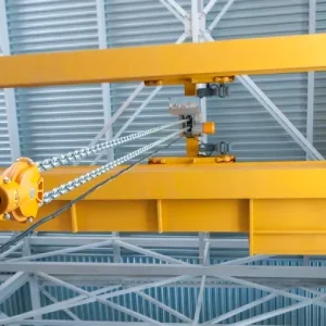
Figs 3 and 4 show another form of invention in which coil chains serve as tension members. Such chains generally comprise welded racetrack-shaped links, interlinked in alternating orientations, as normally used in chain hoists, etc. Idler sprockets designed to smoothly engage with this type of chain replace the pulleys in the wire rope embodiment. In this case the chain guides comprise a pair of U-shaped longitudinal members (72) facing each other to capture alternate chain links between them. Fig 4 is a cross-section through 4-4 in Fig 3 as shows the shape of these members (72) and how they trap the links (74) between them. This gives just enough space so that the chain can freely slide through the guides or channels formed on both sides of the housing (75) as shown.
Near the payout end (36a) of the hoist are rotationally mounted idler sprockets as used in chain hoists. These have grooves (38c), which seat alternate links (74) as in Fig 3, and bridges (38d) between adjacent grooves (38c) to engage the alternating chain links (74a). The load nut has one of the U-shape guide components passing through it. The left and right ends of the load nut are again bifurcated. The alternating links of each chain are retained in the desired position and configuration, preventing bunching, kinking or jamming.
Another embodiment of the invention, again with chain tension members, is also described with a different type of chain guide. This comprises four guide roads at each side of the housing to keep all the links in substantially aligned configuration.
About the patent
This article is an edited version of US patent No. 7,175,162 (application no. 10/635,792) filed on 6th August 2003 by Bruce E Ratcliff of Belmont, California, USA, who is president of the Ratcliff Hoist Co. Inc.. The patent was published on 13th February this year.
Disclaimer
This article is an edited version of the patent and may omit legally or technically important text. To see the full patent go to www.hoistmagazine.com/patents
Marketing
Bruce Ratcliff’s company, the Ratcliff Hoist Co. Ltd. of 1655, Old County Road, San Carlos, California 94070, USA, manufactures 16 coil and 16 rollerless ratchet level hoist of ?-6-t capacity, and compact, light hoist in the 1?-6-t range. It also makes bind-fast, rollerless ratchet chain-type load binders and latching-type load binders.
Fig 3 – A view of the invention similar to Fig 1 but showing the use of coil chains as flexible tension members Fig 3 Fig 1 – An elevation or plan view in section of the first embodiment of the hoist with wire ropes serving as tension members Fig 1 Fig 2 – A sectional view cut on the line 2-2 transverse to the longitudinal direction of the apparatus Fig 2 Fig 4 – A sectional view of the embodiment in Fig 3 as seen along the line 4-4 Fig 4